Every elevator has to be equipped with an overspeed governor
acc. to the Lifts Directive 2014/33/EU.
They are used to stop the lift in case of travelling too fast in either
upwards or downwards direction.
The technical requirements for those overspeed governors are
detailed in the EN81 standards, espc. in EN 81-20 and EN 81-50.
BODE overspeed governors operate the lift's safety gear via the
governor's rope.
Angled groove:
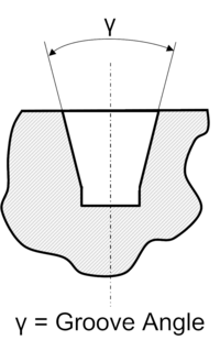
Overspeed governors that are driven by a rope, that itself is driven by the up- and downward movements of the lift's car, use a an angled groove to ensure the necessary traction force.
This angled groove is hardened or soft.
Since the groove is subject to severe wear and tear due to the rope, BODE offers a hardened groove as a standard.
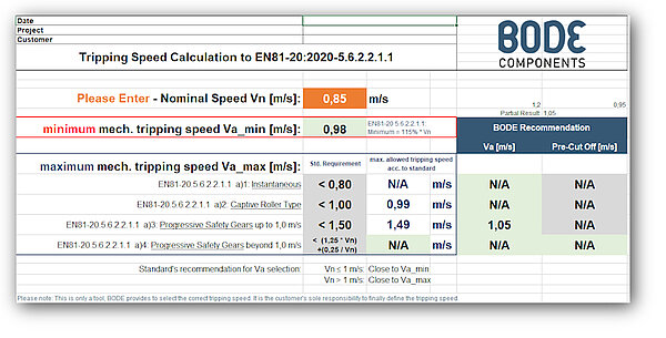
The (over-)speed at which the governors engages the lift's safety gear is called tripping speed va.
This speed is to be determined by the lift manufacturer.
Acc. to EN 81-20, the speed depends on both, the lift's rated speed vn and the type safety gear used.
Our calculation tool considers all the parameters set out in EN 81-20 to determine the tripping speed.
Due to the unknown environment on site and lift components actually used, our tool can only be a help to select the correct tripping speed.
An overspeed governor can only be built and shipped when the exact tripping speed is provided.
Thus, the va is an important parameter that the lift manufacturer has to provide.
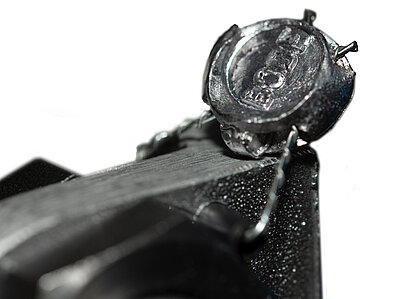
A change of the tripping speed after delivery on-site is not possible, as this setting has to be sealed against reset.
Electrical switch off
Electrical switch off:
The overspeed governor does not only operate the safety gear,
it also switches the lift off via the lift's control system.
The standard requires espc. for rated speeds greater than 1 m/s
a so called pre-cut off switch that switches the lift electrically off
before the overspeed governor reaches its tripping speed.
That's the reason why the overspeed governors are equipped with
(positive break) position switches.
Additional position switches can also be mounted, that signal the
direction of the lift (down- or upwards) when the overspeed
governor was tripped.
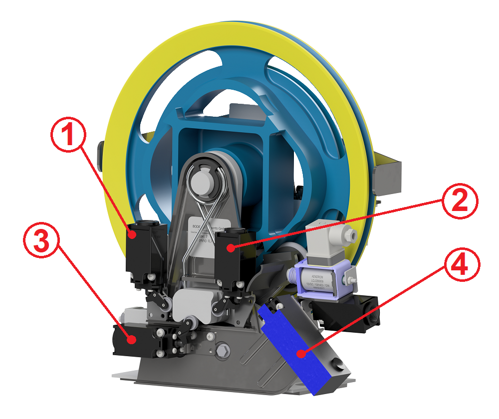
Remote release
Acc. to the occupational health and safety requirements, overspeed governors have to be regularly tested for correct function. To do so, they are deliberately tripped, either through a so called test-groove with a smaller radius, so that the wheel rotates faster or through a remote release. Such a remote release device trips the overspeed governor with the help of a solenoid.
The advantage of this device is the ability to trip and release the overspeed governor from remote. This is especially useful for overspeed governors mounted in confined spaces.
Uncontrolled car movement (UCMP):
Once the car has reached its landing position, it has to be ensured, that it does not leave its position for whatever reason (risk of injury).
The device, that ensures this is called the UCMP-device (sometimes also called anti-creep protection).
This device functions very similar to the remote release, since it also uses a solenoid that blocks the overspeed governor in each landing position.
In contrast to the remote release, the solenoid is energised during lift travel, so that the bolt is retracted. Once the lift reaches its landing position, the solenoid is de-energised, the bolt is pushed out and thus blocks the overspeed governor. Whether or not the bolt is blocking the overspeed governor is signalled to the lift's control system via a position switch on the UCMP-device.