The governor rope is connected with the safety gear of the lift.
Due to the friction between the rope and the groove of the overspeed governor's wheel, created by a tension weight, the vertical movement of the lift is turned into a rotation of that wheel.
This traction force has to be high enough to also engage the safety gear in case the lift travels in either up- or downwards direction at a too high speed.
To ensure this function, the assembly:
Governor Wheel - Governor Rope - Tension Weight has to fulfil certain technical requirements.
Espc. the governor rope has to fulfil following requirements acc. to EN 81-20:2020:
- Compliance with EN 12385-5:2002 (Chapter 5.6.2.2.1.3 a))
- Safety factor for tensile strength ≥ 8 (Chapter 5.6.2.2.1.3 b))
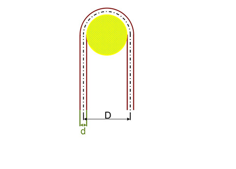
- Diameter ration ≥ 30 (Chapter 5.6.2.2.1.3 c))
- Minimum engagement force FE depending upon safety gear used,
at least ≥ 300 N though (Chapter 5.6.2.2.1.1 d))
Important remark:
The standard does not prescribe a specific procedure to follow to prove compliance with all those requirements.
Thus, it is at the lift manufacturer's discretion to decide, how to document the compliance in detail.
From the mechanical engineering standpoint, the following equations can be determined and can be used for the required calculations.
They are to be considered as guidelines and require further investigations in the relevant standards and considerations of the actual application from the lift manufacturer.
to A): The standard EN 12385-5 is particularly written for stranded steel ropes used in lift applications.
It specifies the materials, the production and testing requirements of suspension, governor and compensation ropes,
used in traction drive and hydraulic lifts.
The standard also describes the specific hazards of these applications.
to B): The safety factor of the rope when the governor has been tripped can be determined as follows:
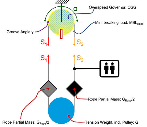
MBKSeil/Smax ≥ 8, with:
- f(µ) = µ * [1 / sin(γ/2)] and
- here µ = µmax = 0,2 and
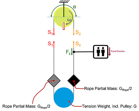
Case 1: Governor top, descending travel:
Smax = ½ [G + GRope] * ef(µmax)*α
Case 2: Governor top, ascending travel:
Smax = ½ [G + GRope]
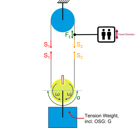
Case 3 & 4: Governor bottom, ascending and descending travel:
Smax = G * ef(µmax)*α / [ef(µmax)*α + 1]
to D): The tensile force FE in the rope to engage the safety gear depends on the safety gear used:
FE has to be at least twice the force necessary to engage the safety gear. It cannot be less than 300 N.
To calculate the produced tensile force, one has to consider different cases: